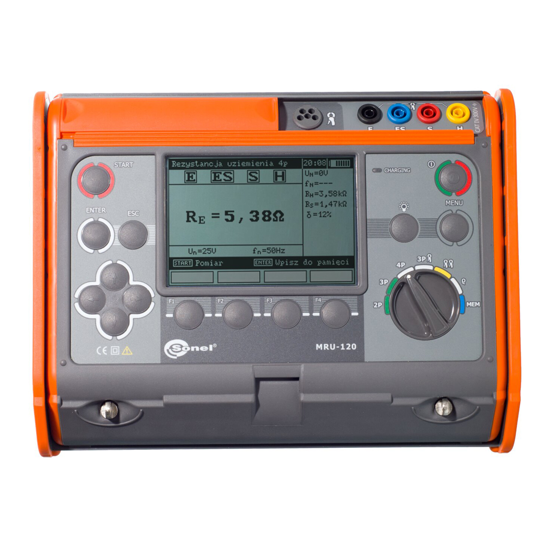
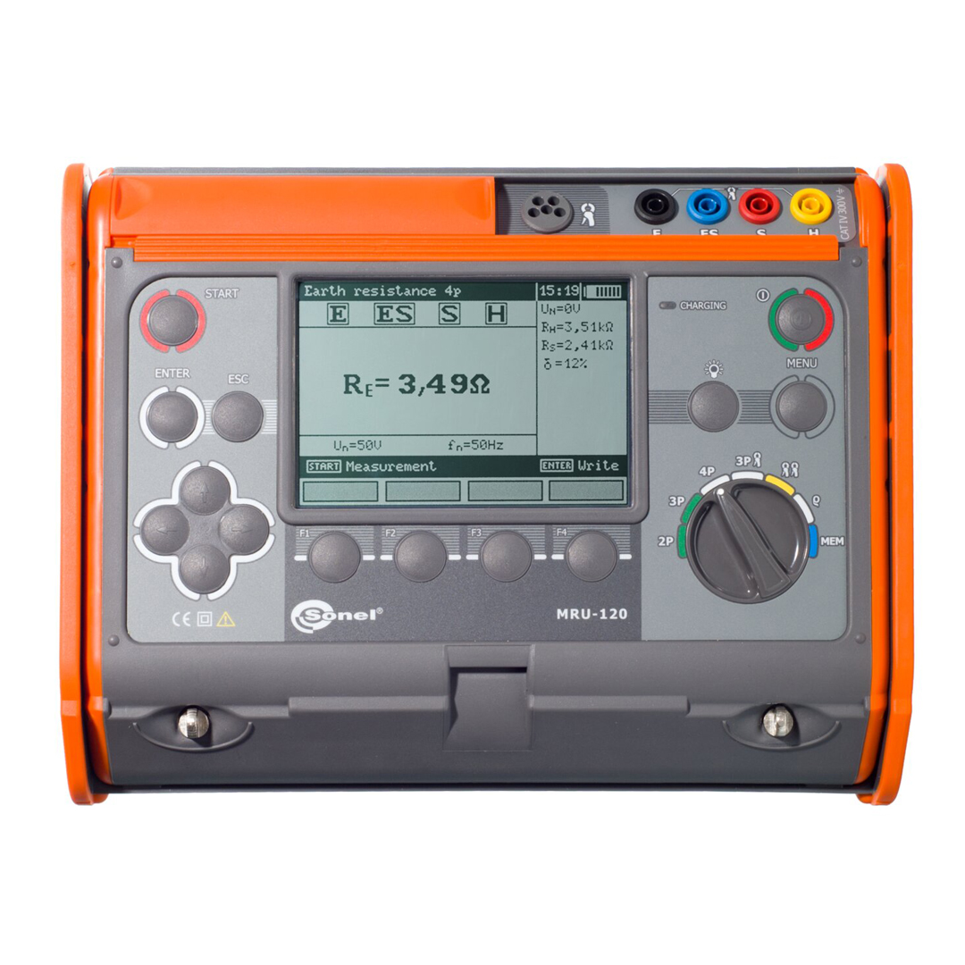
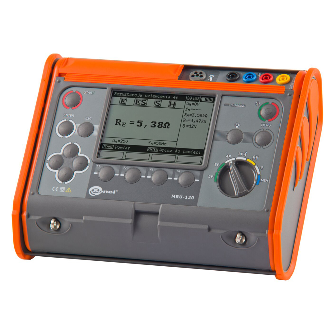
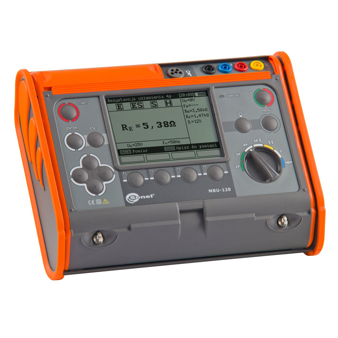
MRU-120
Catalog index: WMGBMRU120
Earthing Resistance & Soil Resistivity Meter
- 3-pole and 4-wire method – measurement of earthing systems using auxiliary probes
- 3-pole method with clamp – measurement of earthing systems with multiple earth electrodes
- Two-clamp method – measurement of earthing system when the auxiliary probes cannot be used
- Soil resistivity – Wenner method
- Resistance of earth connection and equipotential bonding measured using current ≥200 mA with auto-zero function – meets the requirements of EN 61557-4
- Measurement current of 200 mA – facilitates earth resistance measurements in difficult areas (sand, stony soil)
- Measurement of resistance of auxiliary electrodes RS and RH
- Measurement of interference voltage
- Measurement in the presence of interference voltage generated by power networks with frequency of 50 Hz and 60 Hz
- Selection of maximum measuring voltage (25 V and 50 V)
- Automatic calculation of soil resistivity in ohm-meters (Ωm) and ohm-feet (Ωft)
- Memory of 990 measurement results (10 banks of 99 cells each)
- Calibration of clamp used
- Real time clock (RTC)
- Data transmission to the computer
- Battery indication
The measuring methods available in the device allow for comprehensive control of working and protective grounding. The calibration function of the test leads eliminates the influence of their resistance on the result. However, this is just the beginning.
- The four-lead method provides very accurate measurement of the expected small values of resistance – eliminates the resistance of the test leads connecting the meter to grounding.
- Measurement of the continuity of protective connections and equipotential bondings with a current exceeding 200 mA meets the requirements of EN 61557-4 standard.
- Before performing the measurement, the meter checks whether the tested object is a subject to excessive interference voltage, which may indicate additional problems.
Specification
It allows to take the measurements of:
- earth resistance using auxiliary electrodes,
- earth resistance using auxiliary electrodes and clamp (for measurements of multiple earth)
- earth resistance using double clamps (for measurement of earthing when it is impossible to use auxiliary electrodes),
- ground resistivity (Wenner method),
- measurement of continuity of equipotential bondings and protective conductors (meeting the requirements of IEC 60364 – 6-61:2000 section 6.12.2) with auto-zero function – with current 200 mA.
Additionally:
- measurement of resistance of auxiliary electrodes RS and RH,
- measurement of interference voltage,
- measurement of interference frequency,
- measurement in the presence of interference voltage in the power network with frequency 50 Hz, 60 Hz
- selection of maximum measuring voltage (25 V and 50 V)
- introducing the distance between the electrodes for the resistivity in metres (m),
- memory of 990 measurements (10 banks of 99 cells each),
- calibration of clamp used,
- real time clock (RTC),
- data transmission to the computer (USB, wireless),
- indication of battery state.
Electric security:
- type of insulation: double, according to EN 61010 – 1 and IEC 61557
- measurement category: CAT IV 300 V acc. to EN 61010 – 1
- protection class acc. to EN 60529: IP54
Rated operational conditions:
- operation temperature: -10…+55°C
- storage temperature: -20…+70°C
- humidity: 20…80%
Other technical data:
- LCD display: graphic, backlighted
- interface: USB, wireless
- number of measurements carried out of set of batteries: > 500
- warranty: 24 months
Measurement of interference voltage
| Range | Resolution | Accuracy |
| 0…200 V | 0.1 V | ±(2% m.v + 3 digits) |
- singnalling overvoltage 24 V or 40 V rms
- measurement for DC and AC 45…65 Hz,
Measurement of earth resistance (method 3- and 4-pole)
measurement range to IEC61557 – 5: 0,30 Ω…19,9 kΩ
| Range | Resolution | Accuracy | Operating Errors |
| 0,00…19,99 Ω | 0,01 Ω | ±(1% m.v. + 2 digits) | ±(2% m.v. + 2 digits) |
| 20,0…199,9 Ω | 0,1 Ω | ||
| 200…1999 Ω | 1 Ω | ||
| 2,0k…9,99 kΩ | 0,01 kΩ | ±(3% m.v. + 2 digits) | ±(5% m.v. + 4 digits) |
| 10,0k…19,9 kΩ | 0,1 kΩ |
- measurement current: under short circuit >200 mA,
- voltage on open terminals: selectable <25 V AC or <50 V AC,
- frequency of measurement current: 125 (for networks 50 Hz) or 150 Hz (for 60 Hz),
Measurement of continuity of equipotential bondings and protective conductors (Rcont)
measurement range to IEC61557 – 5: 0,24 Ω…19,9 kΩ
| Range | Resolution | Accuracy |
| 0,00…19,99 Ω | 0,01 Ω | ±(2% m.v. + 2 digits) |
| 20,0…199,9 Ω | 0,1 Ω | |
| 200…1999 Ω | 1 Ω | |
| 2,0k…9,99 kΩ | 0,01 kΩ | ±(5% m.v. + 2 digits) |
| 10,0k…19,9 kΩ | 0,1 kΩ |
- voltage on open terminals: <24 Vrms but >4 Vrms,
- measurement current: under short circuit >200 mA,
- frequency of measurement current: 125 (for networks 50 Hz) or 150 Hz (for networks 60 Hz), possible choice of measurement frequency in menu,
- auto-zero function measurement leads
Measurement of resistance of auxiliary electrodes RH and RS
| Range | Resolution | Accuracy |
| 0…999 Ω | 1 Ω | ±(5% (RS+RE+RH) + 8 digits) |
| 1,00k…9,99 kΩ | 0,01 kΩ | |
| 10,0k…19,9 kΩ | 0,1 kΩ |
Measurement of multiple earth resistance with using the clamp and auxiliary electrodes (3p + clamp)
| Range | Resolution | Accuracy |
| 0,00…19,99 Ω | 0,01 Ω | ±(8% m.v. + 3 cyfry) |
| 20,0…199,9 Ω | 0,1 Ω | |
| 200…1999 Ω | 1 Ω |
- voltage on open terminals: selectable <25 V AC or <50 V AC,
- measurement current: under short circuit > 200 mA,
- frequency of measurement current: 125 (for networks 50 Hz) or 150 Hz (for 60 Hz),
Measurement of multiple earth resistance with using double clamps
| Range | Resolution | Accuracy |
| 0,00..19,99 Ω | 0,01 Ω | ±(10% m.v. + 3 digits) |
| 20,0…149,9 Ω | 0,1 Ω | ±(20% m.v. + 3 digits) |
- frequency of measurement current 125 (for networks 50 Hz) or 150 Hz (for networks 60 Hz)
Measurement of ground resistivity
Measurement method: Wennera, ρ=2πLRE
| Range | Resolution | Accuracy |
| 0,0…199,9 Ωm | 0,1 Ωm | depending on measurement accuracy RE with 4p method, but not less than ±1 digit |
| 200…1999 Ωm | 1 Ωm | |
| 2,00k…19,99 kΩm | 0,01 kΩm | |
| 20,0k…99,9 kΩm | 0,1 kΩm | |
| 100k…999 kΩm | 1 kΩm |
L – distance between probes: 1…50 m
Reviews
There are no reviews yet.